Sep.15,2026
If you are asking What are the 7 transformer types?, the answer depends on how transformers are classified. A practical seven-category guide includes step-up, step-down, isolation, power, distribution, instrument, and dry-type or liquid-filled transformers. These categories overlap because one transformer may be three-phase, step-down, liquid-filled, and designed for distribution at the same time.
Before continuing, this article discusses electrical transformers, not the fictional robots from the Transformers franchise. I use “type” to describe a transformer’s voltage role, electrical application, measurement function, or construction method. Understanding these classification layers is important because selecting a transformer only by voltage can cause overheating, insulation failure, harmonic problems, inadequate isolation, or incorrect kVA capacity.
!
A transformer is a stationary electrical device that transfers alternating-current energy between circuits through electromagnetic induction. It normally contains two or more windings placed around a magnetic core, although some designs use an autotransformer arrangement with electrically connected windings.
When alternating voltage flows through the primary winding, it creates a changing magnetic field in the core. That changing field induces voltage in the secondary winding, and the voltage relationship is mainly determined by the ratio of primary turns to secondary turns. The transformer can change voltage and current levels without changing the supply frequency.
A transformer does not create electrical power. In an ideal transformer, power entering the primary winding is approximately equal to power leaving the secondary winding, excluding losses. In real operation, copper losses, core losses, leakage reactance, sound, heat, and auxiliary equipment reduce the usable output.
The following list answers the question directly, while also showing why the categories should not be treated as one universal industry-standard list.
The seventh category contains two construction families rather than one single design. Dry-type transformers use air and solid insulation, while liquid-filled transformers use mineral oil, ester fluid, or another insulating liquid. A transformer can therefore belong to several categories simultaneously, such as a three-phase, step-down, liquid-filled, distribution transformer.
| Transformer category | Main purpose | Typical installation | Common examples |
|---|---|---|---|
| Step-up | Raises voltage for transmission or special equipment | Generating stations, renewable-energy systems | Generator step-up transformer |
| Step-down | Lowers voltage for users and equipment | Factories, buildings, substations | 10 kV/0.4 kV distribution transformer |
| Isolation | Separates circuits electrically | Hospitals, control systems, maintenance areas | 1:1 isolation transformer |
| Power | Handles high capacity in grid systems | Generation and transmission substations | 110 kV or higher power transformer |
| Distribution | Supplies local loads | Utility networks, commercial and industrial sites | Pad-mounted or pole-mounted transformer |
| Instrument | Provides safe measurement and protection signals | Switchgear, substations, control panels | Current transformer or voltage transformer |
| Dry-type or liquid-filled | Defines insulation and cooling method | Indoor or outdoor installations | Resin-cast dry-type or oil-immersed transformer |
The operating principle is similar across most transformer designs, but their winding ratios, insulation systems, ratings, cooling methods, and protection equipment differ. The voltage ratio can be expressed approximately as:
[ \frac{V_1}{V_2} \approx \frac{N_1}{N_2} ]
Here, (V_1) and (V_2) represent primary and secondary voltage, while (N_1) and (N_2) represent the number of turns in each winding. A higher number of secondary turns produces a higher secondary voltage, while fewer secondary turns produce a lower voltage.
The operating purpose determines the design priorities. A transmission transformer may require high insulation strength, low losses, short-circuit resistance, and advanced oil circulation, while an indoor commercial-building transformer may prioritize fire performance, low sound, compact dimensions, and limited maintenance.
Step-up transformers increase voltage from the primary winding to the secondary winding. Power stations use them to raise generator voltage before transmission because transmitting the same power at a higher voltage reduces current and lowers resistive losses in conductors.
For example, a generator may produce power at a medium-voltage level, while a generator step-up transformer raises the voltage for connection to a high-voltage grid. Renewable-energy plants may also use step-up transformers between inverter outputs, collection networks, and the grid interconnection point.
Step-down transformers reduce voltage for distribution and equipment use. A utility system may reduce a medium-voltage network to a lower voltage suitable for commercial buildings, factories, lighting circuits, motors, and electronic equipment.
The difference between step-up and step-down transformers is not simply the physical direction of energy flow. The key distinction is the turns ratio and resulting voltage relationship. A step-down unit still requires correct insulation coordination, grounding, protection, load calculation, and thermal design.
An isolation transformer normally has a one-to-one voltage ratio or a ratio selected to provide a specific voltage while keeping the primary and secondary circuits electrically separate. This separation can reduce the transfer of certain common-mode disturbances and helps establish a controlled secondary grounding arrangement.
Isolation transformers are used in hospitals, laboratories, control systems, maintenance areas, instrumentation circuits, and sensitive industrial equipment. They are also applied where personnel protection, noise reduction, or separation from an upstream supply is required.
An isolation transformer does not automatically make an installation safe. The system still requires correct grounding, overcurrent protection, insulation coordination, and installation according to the applicable electrical code. If the transformer is undersized, its windings may overheat even though the voltage ratio is correct.
Power transformers are generally associated with large-capacity generation, transmission, and major substation applications. They often operate at high voltage and are designed for high efficiency, controlled temperature rise, mechanical strength during short circuits, and long service periods.
These transformers commonly use liquid insulation and radiators, fans, pumps, conservators, pressure-relief devices, oil-level indicators, and temperature monitoring. Protection may include differential protection, overcurrent protection, restricted earth fault protection, sudden-pressure protection, and surge arresters.
A power transformer is selected according to voltage class, rated capacity, impedance, vector group, frequency, tap-changing requirements, short-circuit duty, cooling method, and environmental conditions. A nameplate voltage alone is not enough to determine whether a power transformer is suitable for a transmission or generation project.
Distribution transformers reduce medium-voltage electricity to the utilization voltage required by local customers. They are installed in utility substations, industrial facilities, commercial buildings, residential networks, renewable-energy systems, and compact substations.
Distribution transformers are often energized continuously, even when the connected load is low. For that reason, no-load loss can have a significant effect on long-term operating cost. Load loss, temperature rise, voltage regulation, noise, maintenance requirements, and installation space should be considered together.
A box type substation commonly integrates high-voltage switchgear, a distribution transformer, and low-voltage distribution equipment inside a compact enclosure. This arrangement can reduce field assembly work and is useful for construction sites, industrial parks, commercial facilities, renewable-energy projects, and other locations requiring a packaged distribution unit.
Instrument transformers reduce high system voltage or current to standardized values suitable for meters, protective relays, monitoring systems, and control equipment. The two main forms are current transformers and voltage transformers, also called potential transformers.
A current transformer operates with its primary connected in series with the power circuit, while its secondary supplies a reduced current to a meter or relay. A voltage transformer is connected across the system voltage and produces a lower, measurable secondary voltage.
Instrument transformers require careful attention to accuracy class, burden, insulation level, polarity, ratio, saturation, and protection function. Incorrect selection can result in inaccurate energy measurement or delayed operation of protective relays during a fault.
Dry-type transformers use air and solid insulation rather than an insulating liquid. Common designs include cast-resin and air-insulated transformers, which are frequently installed indoors or in locations where liquid containment and fire-management requirements make oil-filled equipment unsuitable.
Dry-type transformers are used in factories, hospitals, commercial buildings, data centers, transportation facilities, mining projects, and renewable-energy installations. They usually require adequate ventilation because heat is transferred directly to the surrounding air or through forced-air cooling equipment.
Liquid-filled transformers use insulating fluid to provide dielectric insulation and heat transfer. Oil-immersed designs are widely used in outdoor substations, utility distribution systems, renewable-energy collector stations, and high-capacity industrial applications.
The comparison between dry-type and liquid-filled transformers should include more than fire risk. Liquid-filled units may offer efficient heat transfer and high capacity in a smaller active assembly, while dry-type units may simplify indoor installation and reduce liquid-leakage concerns. The final decision depends on capacity, voltage, fire regulations, enclosure, ventilation, maintenance access, climate, and total installation cost.
Power transformers and distribution transformers are both used in power systems, but they serve different operating layers. Power transformers transfer energy between major voltage levels in generation and transmission networks, while distribution transformers supply local loads closer to the end user.
| Factor | Power transformer | Distribution transformer |
|---|---|---|
| Main location | Generation or transmission substation | Local utility or customer substation |
| Operating profile | Often selected for high-capacity transfer | Frequently energized continuously |
| Primary design focus | High voltage, stability, fault strength | Voltage regulation, low losses, size, cost |
| Cooling | Often liquid with radiators, fans, or pumps | Dry-type or liquid-filled |
| Typical application | Grid interconnection or transmission | Factory, building, commercial, or local network |
| Protection | Extensive relay and monitoring package | Depends on rating and installation |
The boundary is not determined by one universal kVA value. Voltage class, utility practice, system position, operating duty, and project specifications all influence whether a transformer is treated as a power or distribution transformer.
The terms “type” and “classification” are often used as if they mean the same thing, but they describe different viewpoints. A type may identify what the transformer does, while a classification may identify how it is built, connected, cooled, or installed.
A transformer may be classified in several ways:
This explains why there is no single universal list of exactly seven transformer types. The number changes according to whether the classification is based on voltage, application, construction, cooling, phase, or installation.
I recommend selecting a transformer in the following order rather than starting with a product name.
This process reduces the risk of choosing a transformer with adequate voltage but inadequate thermal capacity, unsuitable insulation, poor harmonic performance, or an incompatible enclosure.
When I evaluate a transformer supplier, I review more than the catalog category. I check whether the manufacturer can provide design calculations, rated-loss data, factory test reports, wiring diagrams, installation instructions, spare-parts information, and commissioning support for the actual project.
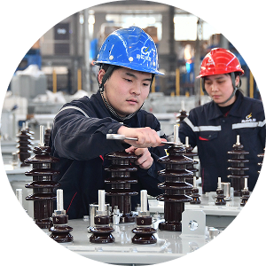
Hebei Gaojing Electrical Equipment Co., Ltd. states that it develops and manufactures energy-saving transformers, high- and low-voltage equipment, box type substations, iron cores, and new-energy charging equipment. Its published company information identifies a production base of approximately 100,000 square meters, more than 600 employees, nearly 100 independent intellectual property rights, and an annual transformer production capacity of approximately 100,000 units or sets.
The company’s listed transformer range includes silicon-steel and amorphous-alloy core designs, three-dimensional toroidal-core transformers, oil-immersed transformers, and dry-type distribution transformers. Its published technical information also describes a 4,000 kVA/37 kV amorphous-alloy three-dimensional toroidal-core transformer type-test result reported in 2023, as well as a 110 kV three-phase oil-immersed three-dimensional toroidal-core power transformer developed in 2015.
For a box type substation or industrial transformer project, I would still match the supplier’s proposed equipment against the project’s voltage, kVA, short-circuit level, enclosure rating, cooling method, environmental conditions, protection scheme, and applicable IEC, IEEE, utility, and local code requirements. Factory scale can support production planning, but project acceptance should depend on verified technical documents and test results.
Several failures result from treating transformer selection as a simple voltage-conversion exercise. Undersized kVA capacity can cause excessive winding temperature, accelerated insulation aging, nuisance trips, and reduced service life. Motor starting, variable-frequency drives, rectifiers, data-center loads, and renewable-energy inverters may also introduce harmonics that increase heating.
Inadequate isolation can transfer disturbances or create an unsafe grounding arrangement. A dry-type transformer installed in a poorly ventilated room may exceed its temperature limit, while a liquid-filled transformer installed without suitable fire protection or spill control may create an unacceptable site risk.
Incorrect impedance can increase fault current or cause poor voltage regulation. Other common errors include selecting the wrong vector group, ignoring altitude derating, omitting surge protection, failing to verify phase sequence, and installing a transformer outdoors without suitable enclosure and environmental protection.
What are the 7 transformer types? The seven practical categories are step-up, step-down, isolation, power, distribution, instrument, and dry-type or liquid-filled construction. These categories overlap, so one transformer may be a three-phase, step-down, liquid-filled distribution transformer or a dry-type isolation transformer for an indoor control system.
The best transformer choice depends on voltage, capacity, application, phase, cooling, insulation, installation environment, protection, and future load growth. I recommend defining those requirements first, then comparing power transformers vs distribution transformers, dry-type vs liquid-filled designs, and the available construction options.
For an industrial facility, commercial building, renewable-energy project, or box type substation, the purchasing specification should include kVA or MVA rating, primary and secondary voltage, frequency, vector group, impedance, losses, temperature rise, cooling method, enclosure, testing, protection, and documentation. This approach makes transformer types easier to understand and reduces the risk of selecting equipment that is electrically correct in one category but unsuitable for the complete installation.
Require More Customized Solutions?
We offer customization to meet your specific needs. Our expert team will collaborate with you to develop the perfect product for you
Navigation
Navigation
Contact Us
Tel: +86 188 3000 9955
E-mail: gjscb@hbgjdq.com
WeChat: zjj9232013
Add.: No.118, Luchan Road, Yongnian District, Handan City, Hebei Province, China
Send in Inquiry
Send in Inquiry